Framework Proposal
Software infrastructure overview
As proposed by prof. Luigi Palopoli in the integration meeting (October the 15th, 2024) in Heraklion, Crete, the software infrastructure will mainly encompass 3 components, as highlighted in the following diagram.
The low-level control of the robot will be based on the RT framework developed by IIT, XBot2. To work, we will need surely a real-time patched Linux kernel, and maybe the Xenomai co-kernel for hard RT applications.
Other soft-RT applications can (potentially) live in another machine. In this category falls all motion and task-planning algorithms, as well as all the estimation methods.
We might also provide non-RT application for data monitoring, review, and post-processing. For this reason, a database will be needed to store all the data.
All these components will communicate through the ROS2 Humble middleware.
Components Functional Design and API specification
Preliminary definitions
Component: an entity that provide some specific functionalities; strictly connected to the implementation as a ROS2 node.
Module: a group of components that provide an higher level functionality.
Package: intented as a ROS2 package, i.e. a software repositories containing source code for 1 or multiple components.
Modules
By exploiting ROS2 functionalities, the final MAGICIAN technological stack will consist of a distributed network of ROS2 nodes that work interactively. Still, to reason at a higher level, we separate different node components in modules based on the node’s semantic and functionality. For this reason, we identify the following areas:
Estimation: comprise all steps that, from the acquisition of the raw data, enable to retrieve a representation of the defect map of a single car.TaskPlanning: comprises all task-level planning nodes;MotionPlanning: comprises all motion-level planning utilities;Controller: comprises all low-level control utilities to interact with the robot;HardwareInterface: hardware abstraction layer;HumanEstimation: deals with the acquisition of the human pose and the consequent motion forecasting;OfflineOptimisation: contains all offline algorithms entitled to analyse the robot-provided data from the production floor in order to analyse and optimise the robot parameters, as well as to improve generalisation capabilities of the provided solution.
Within each module, we expect multiple nodes (components) to exists and run.
It also true that a single component might implement features of multiple modules; an example is XBot2, that will most probably expose the Controller interfaces with a tight connection to the HardwareInterface.
From a high level perspective, this is the main interaction between the modules:
Note: To ease development, we don’t enforce all components of a module to be implemented within the same package. Rather, each partner is welcome to create, maintain, and document its own package, and specify there each executable node which interfaces it specifically implements.
Components
To properly achieve the functionalities of a module, multiple components are required. Since the final architecture will consist of a distributed set of ROS2 nodes, we enforce in this document the minimal set of requirements that each component shall rely on to work, and the output that they must provide to other nodes.
In the following you may find:
interfaces (letter
Iwithin a purple circle): represent an abstract interface with no actual implementation;entities (letter
Ewithin a green circle): represent a concrete and unique implementation of a ROS2 node.
Within each component, there are multiple entries representing the implementation constraint; additionally to the provided sections, consider the following legend:
red squares represent inputs (both topics and services);
green circles represent outputs (topics);
blue triangles represent services that the node exports;
Note: entities cam be regarded simply as ROS2 nodes that export the fixed input-output relationships, while interfaces are used to express
an abstract component whose functionality is only envisioned to make the MAGICIAN technological stack functional, but there’s not (yet) a proper well-thought implementation;
the possibility of having different implementation to realise the same functionality.
Estimation module
This package specifically deals with the sensing and the perception algorithms tight to the car body analysis, and not with the analysis of the human present (which is instead considered in the Human module).
CameraSensorandTactileSensorrepresent the node components of the corresponding sensors; they collect the data, might perform internal pre-processing, and outputs the raw data in a ROS-friendly format;EstimationAlgorithmis an interface component whose responsible to “glue together” the various data coming from the sensors;Localiseris an interface for components that can provide the relative position of pieces within the robotic cell (e.g. to position the base-link frame of the robot w.r.t. the car body). We envision multiple implementation of this interface (e.g. using motion capture system, or marker(less)-based vision system), depending on the availability of the testing facility (e.g. Trento might have a setup which is different from Genova, that is different from the one in TOFAS).
TaskPlanning module
Supervisorimplements the finite-state machine which will orchestrate, at runtime, the execution of the distributed network of nodes.
MotionPlanning module
Controller module
HardwareInterface module
HumanEstimation module
OfflineOptimisation module
API Definition
The previous section outlined the interfaces that each node must implement to work in the system. Here we expand on the details of the topics and services there reported.
Since our work will require the transfer of non-standard data types, we must rely on custom messages and services definitions.
To this extent, it has been created the repository magician_msgs;
there, everyone can specify the expected input and output of each service/topic.
All messages shall be documented as reported in the README of that repository; by doing so, one can refer to the online documentation to have detailed information about the different types.
For a simple example on how to create custom msg and srv files, please refer to the official tutorial on the ROS2 documentation.
Topics
/camera/result(type:magician_msg/camera/Result.msg): provides the identified defects from a image of the vision-based system;/tactile/result(type:magician_msg/tactile/Result.msg): provides the outcome of the defect analysis through tactile sensing;/estimator/state(typemagician_msgs/estimator/EstimationState.msg): provides the current inspection state of the car body (e.g. the map of the found defects, area that has been covered, variance of the estimation…);/car/position(type:geometry_msgs/PoseStamped.msg): position of the car body w.r.t. a common reference frame;/robot/position(type:geometry_msgs/PoseStamped.msg): position of the robot base link w.r.t. a common reference frame;/controller/position(type:geometry_msgs/PoseStamped.msg): desired end-effector position;/controller/velocity(type:geometry_msgs/TwistStamped.msg): desired end-effector velocity;/human/tracked_humans(type:magician_msgs/human/HumanSkeletons.msg): list of all the skeleton data tracked;/human/motion_forecast(type:magician_msgs/human/MotionForecast.msg): reports the predicted motion of the humans;
Services
/estimator/get_defects(typemagician_msgs/estimator/GetDefects.srv): retrieves the currently sensed defects;/task_planner/orienteering(typemagician_msgs/task_planning/Orienteeering.srv): solves the standard orienteering problem;/motion_planner/dmp/time_estimator(typemagician_msgs/motion_planner/dmp/TimeEstimate.srv): estimates the time to move within 2 (or multiple) points using DMPs;/motion_planner/dmp/execute(typemagician_msgs/motion_planner/dmp/Dmp.srv): executes a DMP-based motion;
Extra features
Managed Nodes
To facilitate the overall orchestration of the distributed network of nodes, we might rely on managed ROS2 nodes.
According to such standard, each node internally have a finite state machine of 4 states: unconfigured, inactive, active, finalized.
The following diagram (extracted from the ROS2 design documentation) shows the lifecycle of a node, describing all possible transitions:
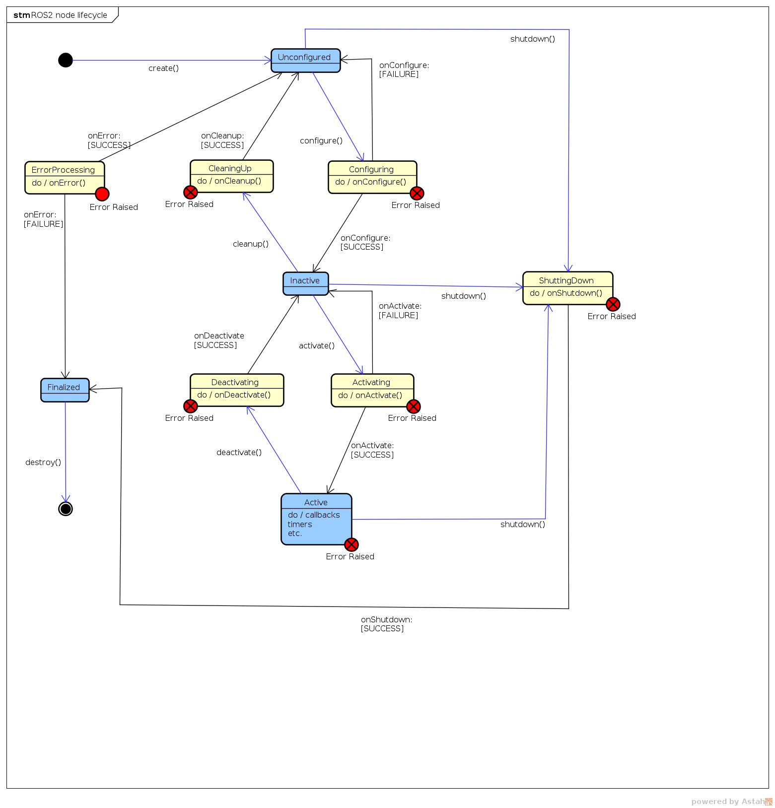
By exploiting this finite-state machine-like behavior for each node, it will make easier to enable-disable particular functionalities at runtime.